The first PCB designed with circuitscript
I have designed the first PCB with a schematic created using circuitscript! The main aim of this design is to create a compact USB-UART bridge using the CH340 chip. Through this design, circuitscript is tested as a tool for generating schematics, netlist and the BOM.
Coding the schematic
The datasheet for the CH340 provides an example schematic and this was adapted for the design. Once this circuit was coded, the next thing was to decide on the connectors.
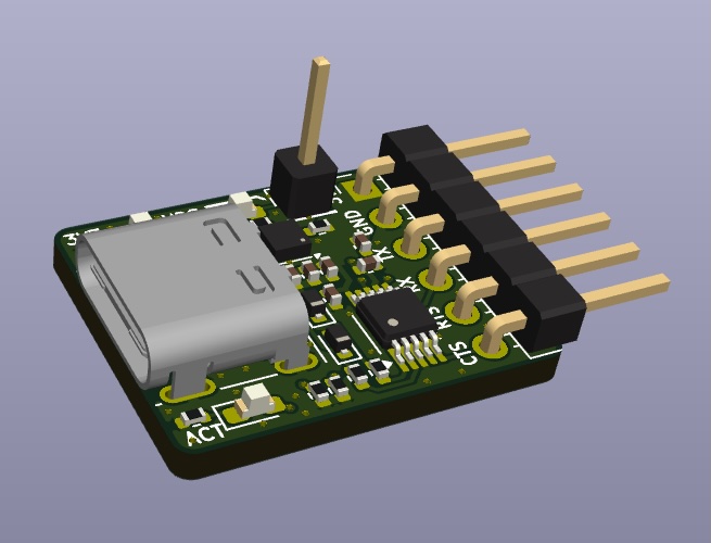
I chose USB-C as the main connector since this is quite common and the board can be used with modern devices. The UART connections are exposed with a right-angle pin-header.
Annotations
When the code is executed, circuitscript assigns reference designators automatically to the components. The -u (update source) option was used with the circuitscript tool to save the refdes comments into the source file. This ensures that the refdes are stable and do not change even if there are code changes. Read more about refdes stability here.
Parameter assignment rules for BOM
The design will be produced and assembled with JLCPCB and the parts used will be sourced from LCSC. Instead of manually assigning part numbers for each component, circuitscript provides parameter assignment rules.
The following parameter rules were used to set the LCSC_part property of the design's components.
set: "LCSC_part":
    type: "res", size: "0402", value:
        0:    "C17168"
        4.7k: "C25900"
        5.1k: "C25905"
    type: "cap", size: "0402", value:
        100n: "C1525"
        1u: "C52923"
    type: "diode", color:
        "RED": "C2286"
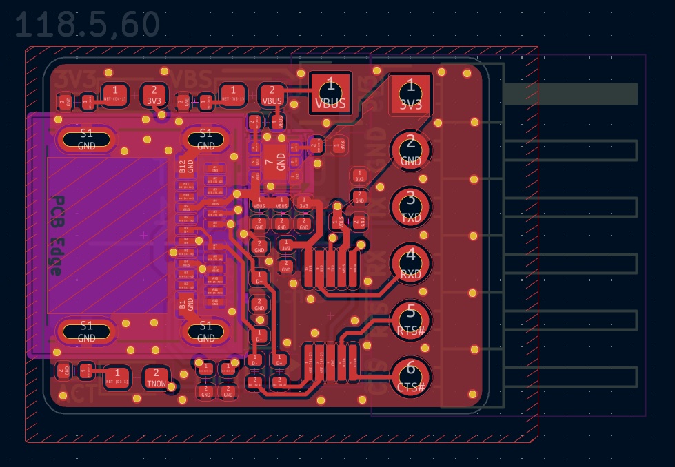
PCB layout
The circuitscript code was exported as a kicad netlist and then imported into pcbnew for the layout. The board was kept compact with small dimensions and only has 2-layers to keep costs low.
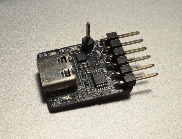
Production & Verification
Once the gerbers are checked, the design was uploaded into JLCPCB for production. Within a week, the finished and assembled boards arrived!
I tested the boards by having two boards communicate with each other and so far it does work!
The final project files can be found here https://github.com/liu3hao/usb-uart-bridge.